Optica 2026
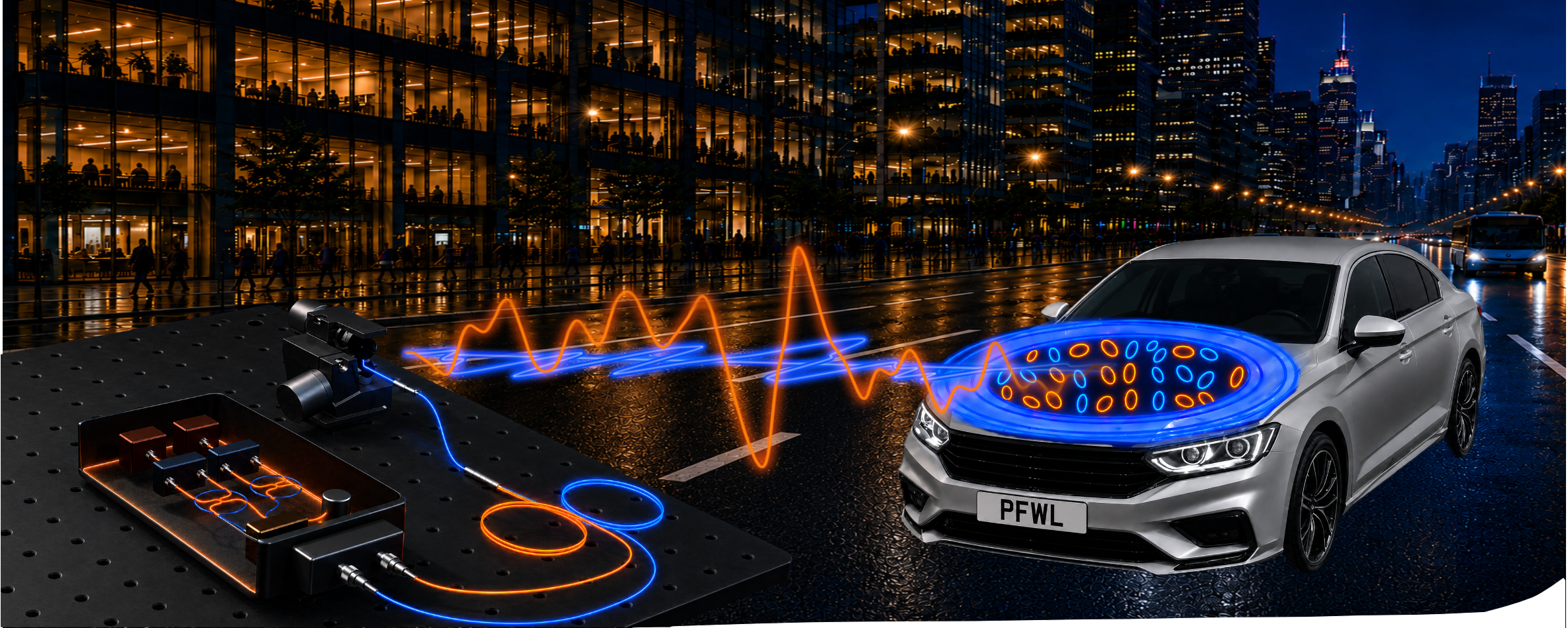
Polarimetric Full-Wavefield Coherent Lidar

Polarimetric Coherent Measurement Model
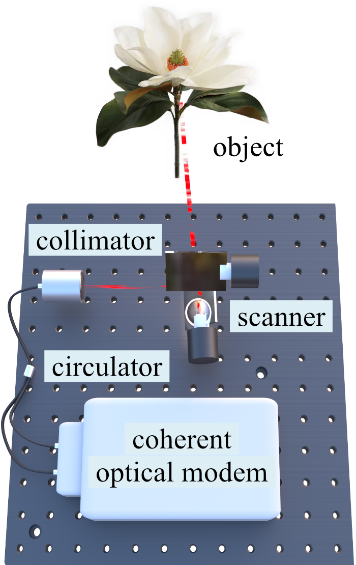
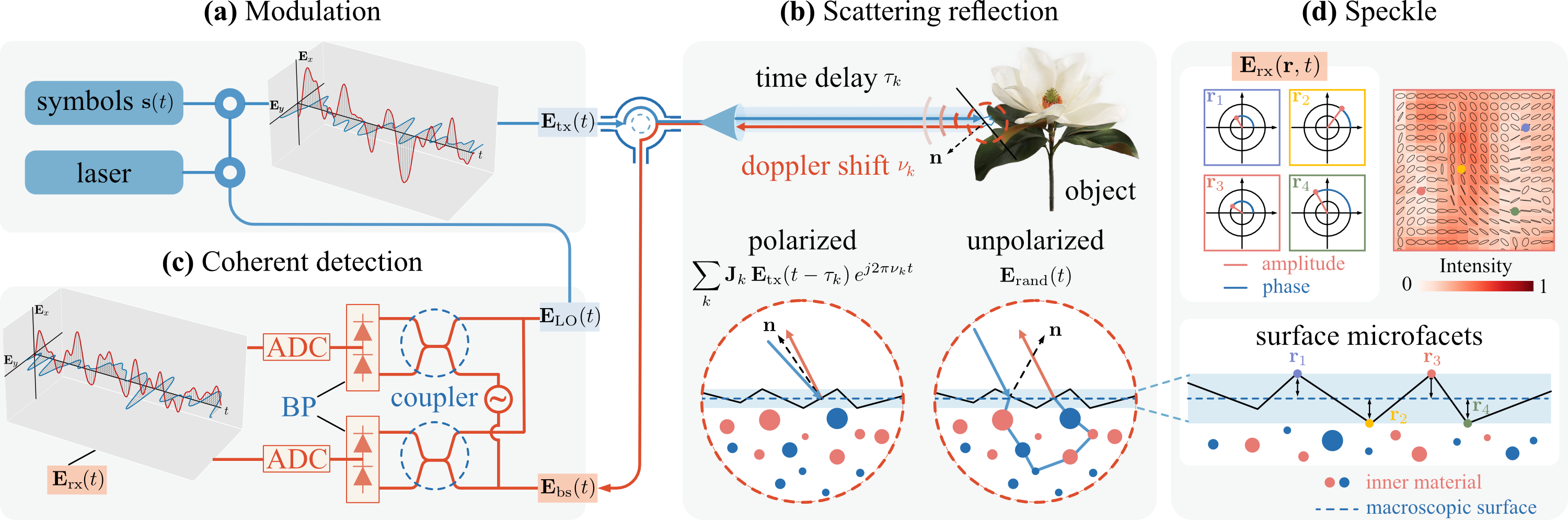
Our system transmits a laser beam modulated by an off-the-shelf coherent optical modem through two orthogonal polarization channels. Backscattered light from the scene carries time delays \(\tau_k\) and Doppler shifts \(\nu_k\) from each surface point, along with a polarized component shaped by the surface Jones matrix \(\mathbf{J}_k\) and an unpolarized incoherent component arising from multiple micro-surface scatterers. A dual-polarization coherent receiver recovers the full optical wavefield \(\mathbf{E}_\mathrm{rx}(t)\), enabling simultaneous measurement of amplitude, phase, and polarization state. Coherent polarization speckle—arising from the interference of contributions from many micro-facets—encodes surface roughness and material properties in its statistical structure.
Scene Reconstruction
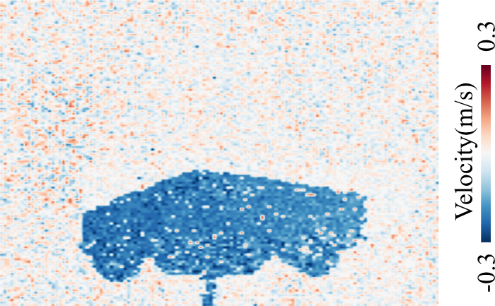
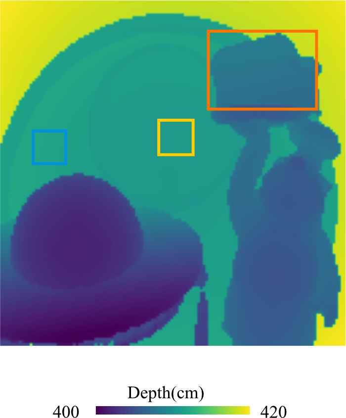
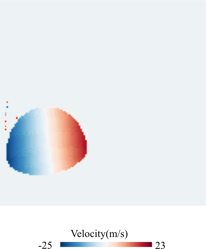
We formulate per-pixel reconstruction as a maximum-likelihood estimation problem. The received two-channel field \(\mathbf{E}_\mathrm{rx}(t)\) is modeled as a complex Gaussian random process whose mean is the sum of time-delayed, Doppler-shifted, Jones-matrix-transformed transmit symbols, and whose covariance is determined by the heterodyne noise and incoherent power \(\beta\). We discretize the Doppler axis onto a fixed grid and jointly estimate a depth–velocity Jones response volume \(\{\mathbf{J}_{k,m}\}\) by minimizing the negative log-likelihood with a sparsity-promoting regularization term. Depth is recovered by integrating the Jones energy \(\|\mathbf{J}_{k,m}\|_F^2\) over Doppler to find the peak-energy delay index \(k^\star\), and velocity is obtained from the dominant Doppler bin \(m^\star\) at that depth. The per-pixel Jones matrix is then decoupled from system distortions via calibrated transmit and receive Jones operators to yield the surface Jones matrix \(\mathbf{J}_\mathrm{surf}\).

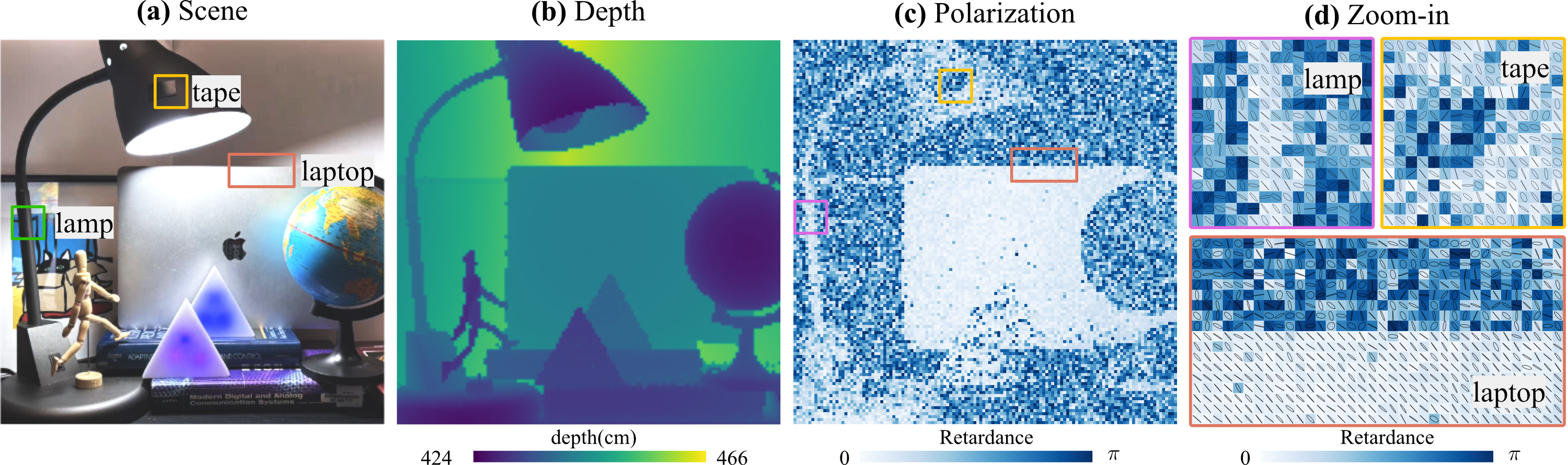
Reconstruction under Ambient Light
Coherent detection enables accurate depth and polarization recovery despite strong, spatially-varying ambient illumination.
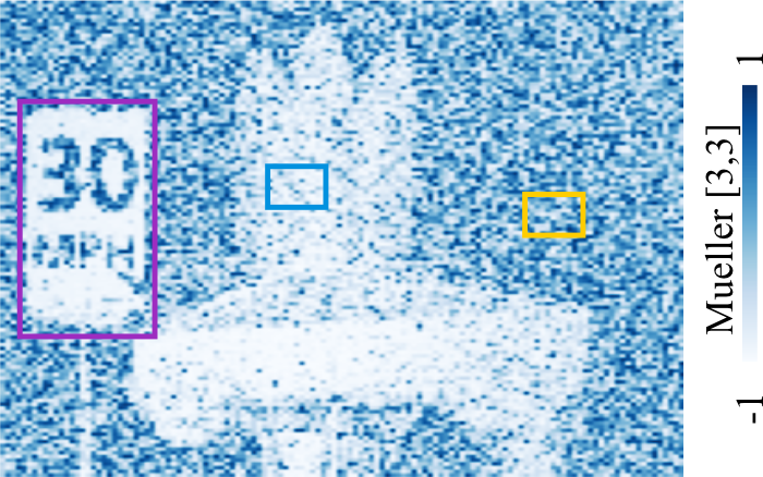
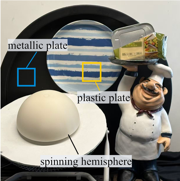
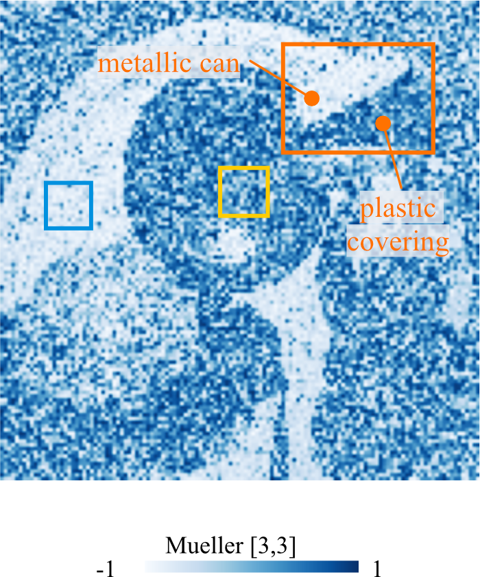
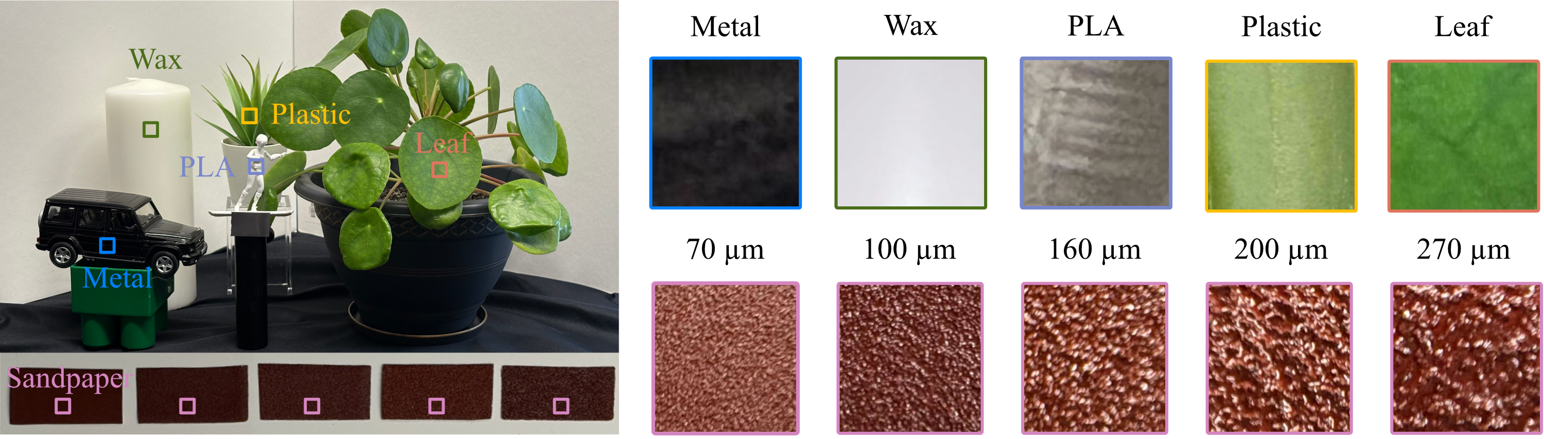
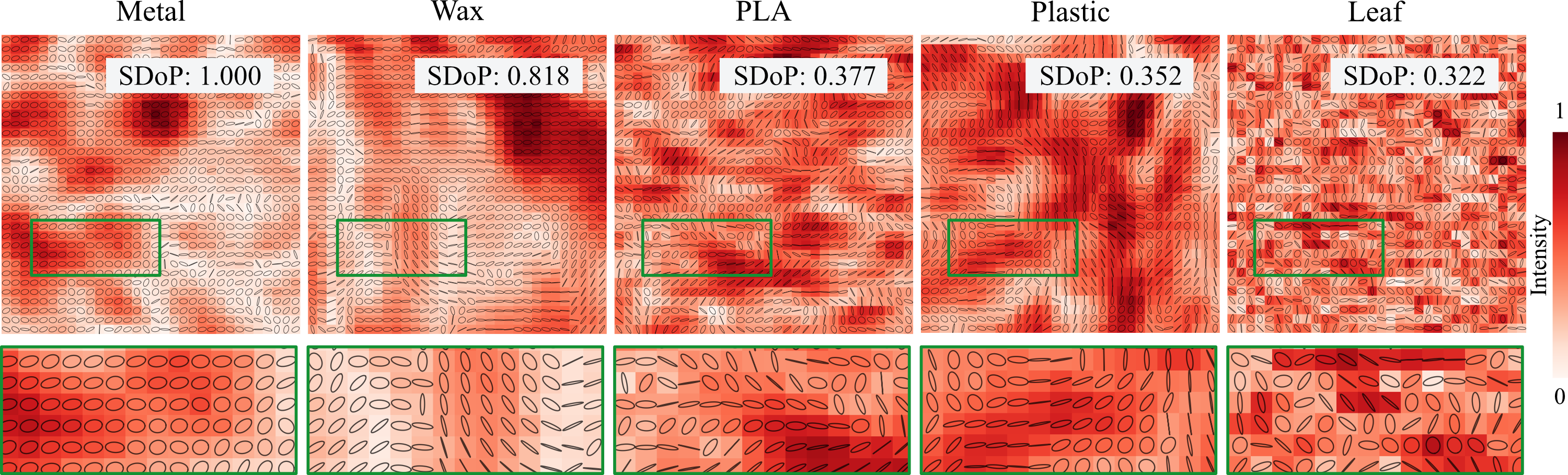
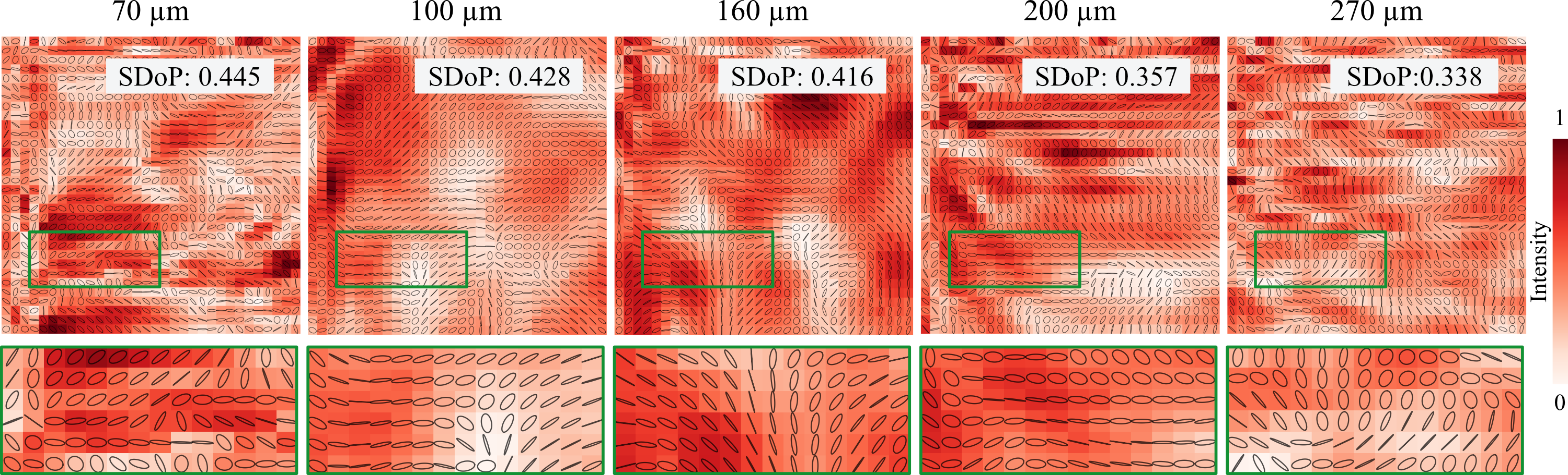
Polarization Coherent Speckle Reconstruction
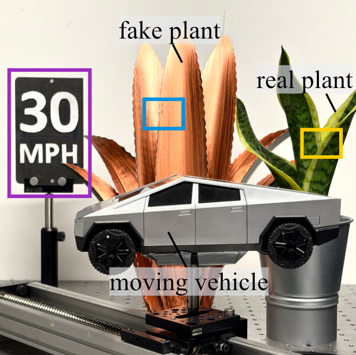
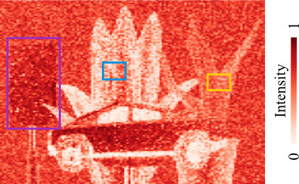
Polarization-resolved coherent speckle reveals material-dependent scattering signatures invisible to intensity-only measurements.
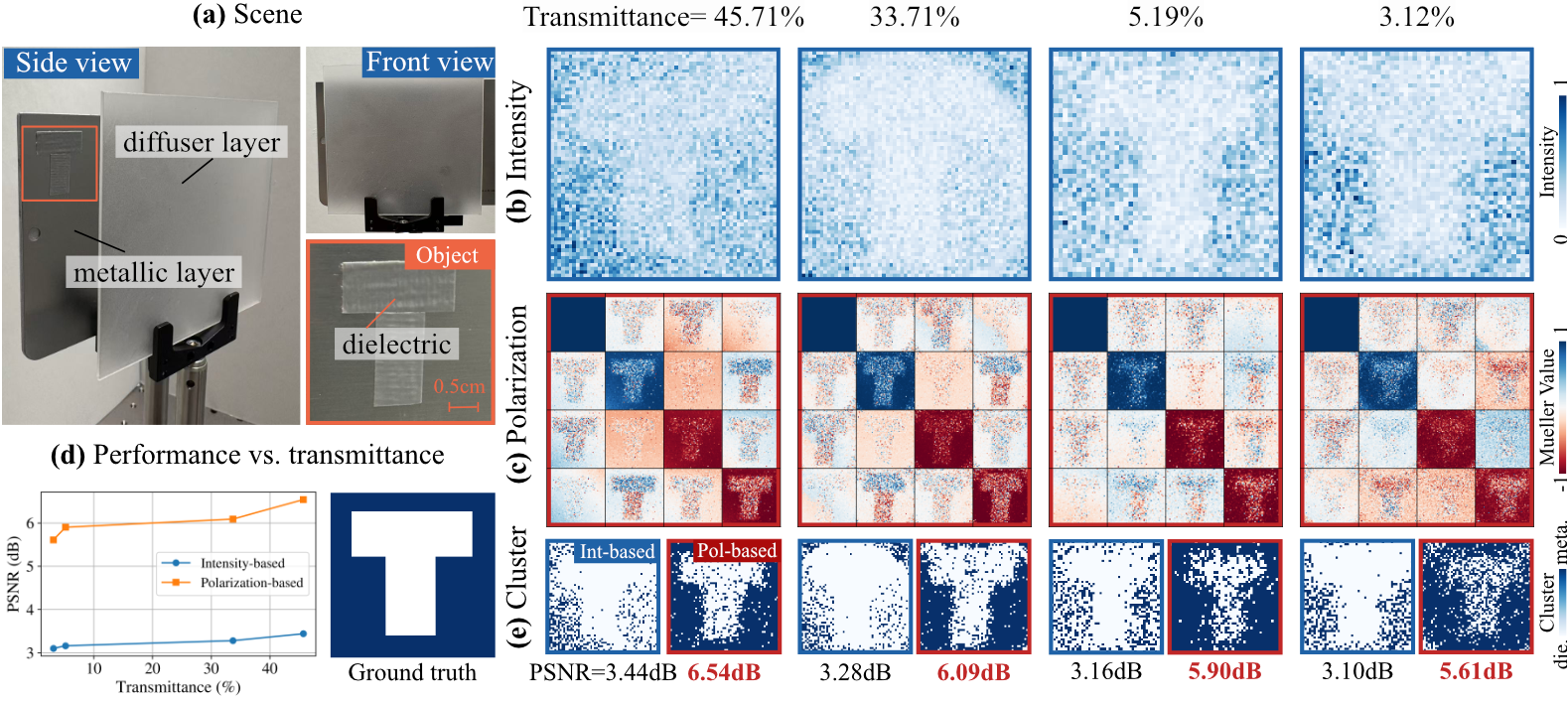
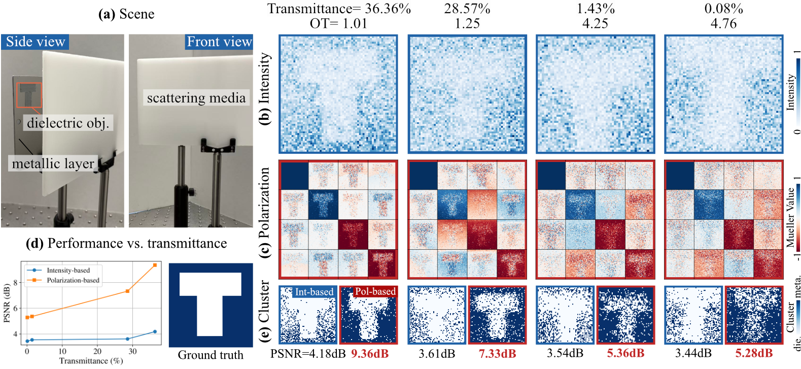
Imaging Through a Scattering Layer
Polarimetric features enable reliable material discrimination through diffuse scattering, where intensity alone provides insufficient contrast.
BibTeX
@article{du2026polarimetric,
  title     = {Polarimetric Full-Wavefield Coherent Lidar},
  author    = {Du, Dongyu and Xie, Andrew and Mirdehghan, Parsa and Buscaino, Brandon
               and Baek, Seung-Hwan and Kutulakos, Kiriakos N. and Lindell, David B.},
  journal   = {Optica},
  volume    = {13},
  number    = {6},
  pages     = {1174--1183},
  year      = {2026},
  doi       = {10.1364/OPTICA.592823},
  publisher = {Optica Publishing Group}
}